A theory and construction of a new device is discussed that is analogous to a transformer. Similar to a transformer, which is two or more inductively coupled coils, a C-stack is two or more capacitance coupled capacitors. The unique behavior is discussed and a case is made that the novel behavior qualifies the device as a new electronic component. The unusual ability to decouple voltage somewhat from current leads to some speculation and experimentation with over-unity concepts. The device is extremely simple to make and is well within the capabilities of most home experimenters.
Although I am not an engineer or scientist, I have a technical background and have been an experimenter for a long time. Tesla has always fascinated me, and many of the things found at the JLN labs site are of great interest to me. Many things on that site inspired the thinking that led me to this idea. The actual mental path to this idea is rather long and convoluted, so I will spare you the boredom and cut to the chase as quickly as I can.
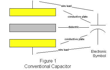
Consider figure 1, that of a conventional capacitor. A capacitor is made up of two, parallel conductive "plates" (films, foils, etc.) separated by an insulation material known as a dielectric. Almost any non-conductive material can be used as a dielectric, but some are much better than others. In general, the larger the conductive plate surface area and the closer the two plates are together, the higher the C value.

The C value is the metric used to rate the ability for a capacitor to store energy. It is stated in Farads. The actual energy stored in a capacitor depends on the voltage. The energy stored in a capacitor for a known voltage is
![]()
where J is expressed in joules (watt-seconds). Notice that because the voltage is squared, small changes in voltage make a rather dramatic difference in the energy stored. The voltage rating, therefore is important, and is governed primarily by the thickness of the dielectric and its breakdown voltage.
The theory of why a capacitor can actually maintain and hold a charge is an important concept.
The conventional wisdom states that,
…although an insulator cannot conduct electric current, it can respond to an electric field in another way. The molecules of all substances either normally have a non-uniform distribution of electric charge within them or assume such a distribution under the influence of an electric field. Such molecules are known as polar molecules and behave as though one end is positively charged, and the other negatively charged.
"Physics",Arthur Beiser, Cummings Publishing, ISBN 0-8465-0521-5
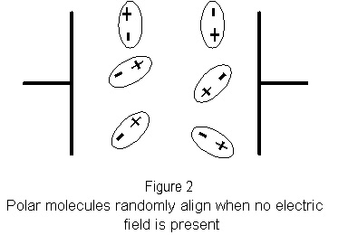
In an assembly of polar molecules when there is no external electric field present, the molecules are randomly ordered (figure 2).
When an electric field is present, it acts to align the molecules opposite to the field (figure 3).
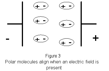
It is this electric field, also known as the Electro Motive Force (EMF) that aligns the polar molecules in the dielectric, which in turn "hold" the surplus of electrons on the negative plate and the deficit of electrons on the positive plate, which constitutes what is known as the charge on the capacitor. The charge will remain unless an electrical circuit path is established for the charged poles to discharge to each other, thereby reaching equilibrium. The circuit path need not be conventional wires. Ionized air works quite well and is responsible for capacitor "leakage" overtime.
The term C-stack I coined for lack of a better term. It refers to a stack of capacitors, but this is already in trouble. Stacking capacitors has been a practice for a long time by the manufactures of capacitors to either increase their C value or increase their rated voltage. If the capacitors are "wired" in parallel, their C value will increase. If they are connected in series, the voltage rating will increase and their C value will decrease.
Capacitors hooked up in either series or parallel, or some combination of both, are generally referred to as capacitive networks. I hope to make a case, that although there are strong similarities to my device and a capacitive network, the behavior is different enough to warrant considering it a new component and not a network.
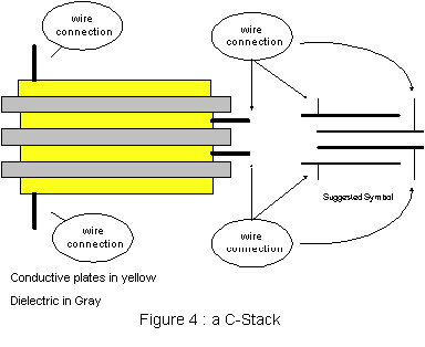
Picture four conductive plates, instead of two, all separated by dielectric material. That is, in essence, a C-stack. The basic difference of this device to capacitor stacks used in manufacturing is that there is no electrical connection between any of the plates.
This may not seen much of a revelation at first, but consider what must happen to the inner set of plates if a charge if placed upon the outer plates.
If an EMF has a sufficient intensity to place a charge on the outer plates, then it must, necessarily, affect the inner plates, because they are intrinsically part of the dielectric for the outer plates. If capacitor theory is correct, a charge distribution of the polar molecules in all of the dielectric material must take place, even though no electrical connection has been made to the inner plates.
So what happens to the inner plates? What would happen on the outer plates if one placed an input signal on the inner plates?. (Figure 5).
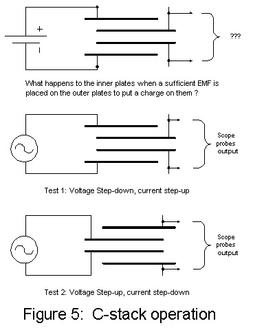
To find out, I constructed my first C-stack out of 4 pieces of copper foil, each 6" x 6". I separated them with .0125" thick vinyl, found in hardware stores to protect furniture (polyethylene would have been much better).
I used a digital capacitance meter to test the value of the inner versus the outer plates. As expected, the outer plates had much less capacitance due to their much greater distance apart. The capacitor defined by the outer plates was .499 nano-Farads, whereas the capacitor defined by the inner plates was 1.977 nano-Farads.
I used a signal generator attached to the outer plates and put the scope probes without a load to the inner plates. After sweeping through several frequency ranges, I selected one that appeared to have the greatest output.
With a 2.9 MHz signal at 10 volts on the outer plates, I observed an 8 volt signal on the inner plates.
Before we discuss the implications of this, let us take a detour and discuss a conventional model to explain the behavior. So far, getting a voltage step-down is not unexpected and could be readily explained using network theory, allowing for measurement errors.
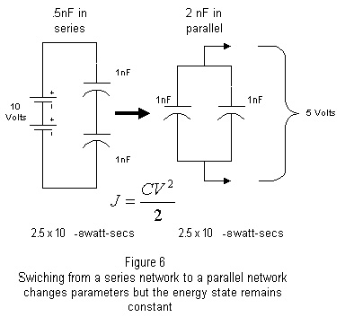
Consider figure 6. In the left hand circuit, assume two 1nF (1 x 10^ -9) capacitors are in series and they are being charged by a 10 volt source. The C value for the two capacitors in series is

Therefore, the energy stored is ![]() Or .(5nF *
10v^2) / 2 = 2.5 * 10 ^-8 joules or watt-seconds.
Or .(5nF *
10v^2) / 2 = 2.5 * 10 ^-8 joules or watt-seconds.
Now, suppose that after the charge has been placed upon these capacitors, that the configuration is changed to the parallel network illustrated on the right hand side of figure 5, without discharging them.
Because the two capacitors were initially in series when the
charge was applied, when we break them apart, they effectively
divide the voltage between them, halving the voltage. The
capacitance, however, goes up, for a parallel configuration,
where the C value is defined by ![]() so that
C = 2nf, and the energy stored is, again,
so that
C = 2nf, and the energy stored is, again, ![]() or (2nf * 5v^2)/2
= 2.5 * 10^ -8 joules or watt-seconds.
or (2nf * 5v^2)/2
= 2.5 * 10^ -8 joules or watt-seconds.
Notice that the energy state did not change, just the parametric values between the two configurations. Thus, network theory would predict that although the parametric values can change by shifting the network configuration of discrete components, the energy state would remain the same.
Lets return to the C-stack experiment and see what happened.
Well, as you might expect, the capacitance values come very close to the theoretical values because the plates of both capacitors were exactly the same, only the distance between them was different. We see that the outer plates .499 nF, was very close to the theoretical .5 nF predicted by two capacitors in series and the, inner plates 1.977 was fairly close to the predicted 2 capacitors in parallel computation of 2 nF.
The expected drop in voltage, however, should have been to 5 volts and I observed 8 volts. So lets see what happened to the theoretical energy states.
| C-Value | Voltage | Watt-Secs | |
| Outer plates (input) | 4.99E-10 | 10 | 2.495E-08 |
| Inner plates (output) | 1.977E-09 | 8 | 6.3264E-08 |
| output/input | 2.53563126 |
In theory, the output energy state was two and half times the input !
Now, to be sure, this had to be measured. The method I chose was to measure both the input and output across a 2.1 ohm load resistor. By measuring the voltage across a known load, the amperage can be computed. The output power is then volts times amps. If the theory was correct, I should see a higher output power than the input. If the device is acting as an unusual transformer, then EI1 should equal EI2. Once again the parametric values for voltage and current will be different on each side of the equation, but their products should be equal, as they would be in a conventional transformer.
Sadly, this was not the case. In fact, the power was much lower than predicted by the transformer model, let alone the .5*CV2 model. I am embarrassed to say that I was so disappointed by the results, that I forgot to record the actual numbers, or I would have presented them. Even if I had, I was not measuring RMS values, but just looking for peak-to-peak values as an indication of relative changes. These experiments should be replicated with much better equipment and skill than I had at my disposal.
It wasn't until a few days later that the significance of what I observed struck me. Both predictions were based upon conventional models. The very fact that neither model predicted the result, strongly implied that the device was, in fact, unconventional.
In a conventional capacitor, if the capacitance is known, and the voltage is known, and the capacitor is allowed to charge to that voltage, then the energy stored must be .5*CV2 . This was not the case.
In a transformer, the input voltage multiplied by the current must equal the output voltage multiplied by the current. This was not the case.
Granted experimental error due to measurement errors and inefficiencies of homemade devices must be taken into consideration, but they should only account for several percent, not several orders of magnitude!
This is the basis for my case that a C-stack is not merely a capacitive network, nor is it an unusual kind of transformer.
The real question became, what would explain the results that I did get, and is the device useful?
I believe that the reason the current did not manifest on the output side was because it simply couldn't. Recall that the inner plates are not electrically connected to the outer plates, so current simply could not flow. However, the current was not zero, just very low. This might be a case, as my father-in-law has suggested, for inductance coupling. Nevertheless, I do not believe this to be true because EI1 should have been equal to EI2, or at least close for an inductively coupled system.
I believe that the two sets of capacitors are capacitance coupled by virtue of sharing their dielectrics and the coupling due to the EMF was enough to create the voltage potential on the output plates. Because the output plates did not have a source of surplus electrons (a power source), the only current that moved was essentially those electrons available in the measurement circuit.
Now, this leads me to predict some
On November 5th, 1901 Nikola Tesla was granted U.S. patent 685,957, entitled "Apparatus for the utilization of radiant energy". It is a fairly simple patent, all of 5 pages. It is an extraordinary idea. Picture a capacitor aligned vertically. Further, picture the top wire attached to a large conductive plate exposed to the sun, and the bottom wire attached to earth ground.
According to Tesla, the radiant energy of the sun caused the large conductive plate to take on a positive charge. His explanation as to why this happened may be viewed dimly with conventional wisdom. It could very well be that what he observed was a form of the photo static effect, the same that is used to make Xerox copies. Incoming light would dislodge electrons from the surface of the metal plate, causing it to become positively charged.
Once the photo plate has a positive charge on it, it would, in turn, remove electrons from the top plate of the capacitor. That would, in turn, cause an EMF charge distribution to take place in the dielectric, which would, in turn, cause a surplus of electrons to accumulate on the opposite plate, if there was a source for them. As it turns out, earth ground is a huge supply of free electrons and provided the source of the surplus electrons. The net effect is that capacitor becomes charged. Tesla invented the first electron pump.
There have been others that have built upon Tesla's ideas. Jean-Louis Naudin's site, JLN Labs ( http://jnaudin.free.fr ) has a good deal on Tesla Technolgy, and some very interesting experiments with electron pumps that indicate the possibility of over-unity. There are even some Russian patent replications of similar devices.
A common problem these devices have that limits their practicality is that they require their input side to be electrically isolated from their output side. The output side is typically the side connected to earth ground, either directly, or via ionic coupling. The input side must not be connected to earth ground, or the circuit will draw electrons from the power supply rather than the environment, obviating its usefulness. To get around the coupling problems, the devices often use batteries on the input side, which also limits their practicality.
It occurred to me that a C-stack is inherently isolated, so it should be possible to build an electron pump using a C-stack to isolate the input from the output. The output side of a C-stack could provide a voltage potential that by nature prevents it from drawing current from its own power supply. The environment, specifically earth ground, would supply the surplus of electrons required to complete the charging of the capacitor. One criteria would be that the voltage be high enough to be of ionizing potential to reject positive ions from some sort of antenna or pin farm.
I performed the following experiment on June 12th of 2001 with some encouraging results.
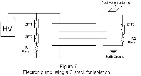
The box labeled "HV" in figure seven was the power supply from a Tesla toy called a Laser Ball. This engaging desk ornament throws a shower of lightning bolts between inner and outer glass spheres. I was delighted to find out that the bulb simply comes out and is supplied by a single wire! I have no idea what the actual voltage was, however.
ZFT1 - 3 were Radio Shack supplied Xenon flash tubes, each with a trigger voltage of about 4Kv. I put two of them in series with a .01 ohm load resister on the input side. The idea was that the high voltage supply would begin to charge the outer plates. When it reached the 8Kv breakdown voltage of the tubes, it would discharge through the resistor, and start the process all over again.
The output side of the C-stack used a single Xenon flash tube in series with another .01 ohm resistor, because of the voltage reduction inherent in the configuration. In this way, I hoped I could measure the current and voltage across both resistors and compare the results.
Unfortunately, I do not have high-voltage test equipment that could measure either the voltage or the current. But I can tell you that the output side of the device glowed much brighter than the input side. I am not jumping to conclusions that this is over-unity, its probably just due to the increase in current. But to know for sure, this experiment should be replicated with much better equipment than I had.
A conventional voltage doubler requires two discrete capacitors and diodes to double the voltage. It also takes an AC signal and yields a DC potential. A C-stack can be configured to step-up or step-down simply by which set of leads you select, inner versus outer respectively. It would be a single component solution that would yield AC from an AC signal. Designed appropriately, C-stacks could be manufactured to have step-up or step-down ratios that are not multiples of 2, and could even be non integer values.
The disadvantage that I see is that if a voltage increase were desired, the AC signal will have to be in its narrow resonant frequency band, which can be quite high for small devices.
Regardless of the mode (up or down), the input plates in a C-stack are electrically isolated from the output plates. This makes a degree of current limitation possible without adding appreciable resistance. In fact, one of Tom Bearden's requirements ("THE FINAL SECRET OF FREE ENERGY", A.D.A.S. 1993) is that the voltage potential be decoupled from the current source, such that the voltage, only, is supplied by the device, and the current is drawn from elsewhere, presumably from the environment.
Over-unity observations have been claimed in non-linear ferro-electric capacitors (see the "VariCond" references and The Nicolay Zaev Generator . at the JLN Labs site.) Perhaps a C-stack made with Barium Titanate and Barium Ferrite ceramics would yield non-linear results.
Electrets can also be made from Barium Titanate. Electrets are unusual capacitors that are permanently polarized, meaning that they have a permanent charge distribution "baked" into their dielectrics. They actually will charge themselves overtime. This may have some interesting implications with C-stacks used in environmental electron pumps, or VariConds, or both…???
In conclusion, I believe that this device is a unique component. I base this on the fact that its observed behavior does not appear to conform to standard network or transformer models.
I also believe that the device is useful, although there may be better alternatives to given functions that it would perform. It appears, however, to be more simple and cost effective than to most of its alternatives.
I have noticed that the device will also work in the reverse configuration. One can use the inner plates as input, and the outer plates as output and get a voltage increase and a current decrease. This appears only to work at its resonant frequency, however. (You can expect that the resonant frequencies of devices on the scale that I built will be in the 3 - 4 MHz range, larger devices will be less). The resonant frequency will be a narrow band and appears out of nowhere as you frequency sweep. The original configuration (outer plates as input = voltage step-down) is much less sensitive to frequency.
I have also built devices where the inner and outer plates were not exactly alike. I used a copper mesh for the inner plates one time expecting the capacitance to be less due to all of the holes. Surprisingly, the capacitance was astonishingly high. Apparently, when the mesh is made, it is made from a solid sheet. The holes are not actually punched out, but are punched and folded back, creating much more surface area than a flat plate. The .5*CV2 value for the output was 132 times that of the input !!! Too bad the actually power out wasn't as high. But, there still may be a way to get there if we can figure out how to charge the plates from the environment. The C-stack gets us half way there because the voltage potential is there, and it is inherently current decoupled from its power supply.
I would like to encourage all who are interested to replicate my experiments and try new ones. Not having the engineering background, or the equipment, puts me at somewhat of a disadvantage.
I am still not sure whether the device is useful, or if my theories explain its behavior. I believe the device is useful and would love it if some of the more advanced among you would try it with some of your experiments, particularly those in Tesla devices like electron pumps. Your critiques are important to the discovery process.
Additionally, your input, and your experimental results are important to me because of the way the patent laws work in the U.S. We are still on a "first to invent" rather than "first to file" basis. Therefore, I am somewhat protected by this publication and other mechanisms for up to a year, in which time I will be evaluating this idea. Your experiences will help me decide how viable the idea is, and whether to go forward with it or not.
Good luck, and please keep me informed of your results.
Cris Paltenghe
Oak Park, CA.
June 16 2001
Cris_Paltenghe@yahoo.com
Return to Tesla Exploration home page